Designing and building a digital thermometer
This project page was updated on the 28th of July, 2014. Please scroll down to see the new additions.
Introduction
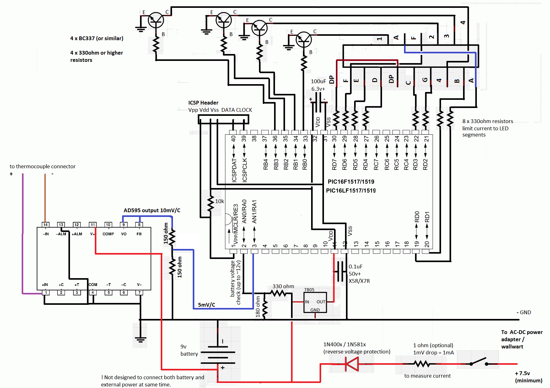
In this video tutorial, a digital thermometer is designed and built using the commonly available AD595 thermocouple amplifier and an 8bit PIC16F1519 microcontroller.
Description
Part 1 of this video tutorial starts by introducing viewers to the reasons why a digital thermometer is useful for a hobbyist and why such a tool differs from other tools, such as infrared thermometers.
Infrared thermometers have the advantage of being able to measure the temperature of a surface at a particular distance, but they some disadvantages:
- some materials are measured incorrectly due to their emissivity - more expensive infrared thermometers allow user to adjust this value
- they measure a small area in front of the thermometer, which changes with the distance - it's difficult to measure tiny heat sinks or small ICs
- they often have a laser point that only accurately points to the measured area when the infrared thermometer is within a certain distance
- they can not be used in certain environments, for example when trying to measure the temperature inside a reflow oven
A lot of digital multimeters are currently capable of measuring temperature using cheap thermocouples, and there are also very cheap temperature meters available on eBay and other online stores. Prices for such a meter, including a K type thermocouple, can be as low as $10. However, buying such a tool won't give you the pleasure of knowing you built your own tools and you don't learn anything by doing that. While the components chosen for this project are more expensive compared to a commercial tool, the knowledge gained by building one with your own hands makes up for it.
The design process starts off by defining the requirements for this thermometer:
- must be able to measure from 0 degrees Celsius up to at least 500 degrees Celcius
- must be able to measure as little as 0.5 degrees Celsius difference
The first requirement would make this thermometer very useful for measuring temperature of solder iron tips or temperatures inside reflow ovens, both use cases difficult otherwise for infrared thermometers. The second requirement is simply a challenge, to insure that the thermometer will have a good accuracy within the temperature range.
For this project, a few components were chosen simply because they were already purchased as spares for other projects and because they met the requirements. The parts used may not be the cheapest available and there may be newer parts that have the same performance or functionality. All parts for this project were purchased from Farnell because it is physically close to author's address and have reasonable shipping times and costs. Parts are available from other good part stores - please scroll down to the footer for a list of recommended online stores to buy from.
The first part chosen for this thermometer is a cheap K type thermocouple supplied by Labfacility.
The part is only rated for up to 250°C but the author suspects this low rating is simply due to the isolating material used and due to the small diameter of the wire. For designing, testing and building this project, this thermocouple is good enough - if it turns out the thermocouple can not handle temperatures higher than 250°C, it's always possible to purchase one of those more expensive high temperature thermocouples that can measure up to 800-1350°C.
K type thermocouples output a small voltage as the temperature changes where the two different alloys are welded together - for K type thermocouples this voltage is 40.44 mV/°C. Such voltage is too low to be measured reliably using a regular multimeter and the output of a thermocouple so a thermocouple amplifier IC or a precision operational amplifier is required to boost this voltage to levels which can be measured easily.
The Analog Devices AD595 used in this project is one of those thermocouple amplifiers. As it was readily available as spare from other projects, its biggest disadvantage is the high price. Putting that aside, the IC has several features that make it a very good choice:
- it is available in DIP package, making it easy to solder onto a prototyping board
- it has built in ice point compensation, simplifying the design and improving the accuracy of the amplifier
- it amplifies thermocouple voltage to an easy to measure 10mV/°C
- it works powered from a simple, positive only power supply and with as little as 5V, if only positive temperatures need to be measured.
By design, the IC is only capable to output a voltage that's 2V lower than the power supply voltage - with a small 5V power supply, the AD595 would only be able to correctly report temperatures up to about 300°C. As the requirements call for a maximum of 500°C, the IC will have to be powered using at least 7.1V, which makes choosing a battery for this project a bit easier.
AD595 will simply amplify the small voltage, so its output will still be non-linear. A microcontroller takes care of the converting AD595's output voltage to the proper temperature value.
In order to have that 0.5°C precision (or better), a microcontroller with at least a 10bit ADC is needed. Also, as most power supplies are not stable enough, a voltage reference is needed. Due to these requirements a Microchip PIC16F1519 was chosen for this project. This chip has a 10bit ADC and an internal voltage reference with configurable levels (1.024v, 2.048v, 4.096v), which allows output voltage measurements of approximately 2mV or 4mV per bit, making it capable of showing the actual temperatures with a precision better than 0.5°C.
It is possible to use other microcontrollers - for example Arduino - but an external voltage reference may be needed in that case, which increases complexity and cost of this project.
Instead of using cheap LCD 2x16 displays, a seven segment LED display is used, giving the opportunity to explain how these displays work and make the tutorial more interesting.
The only suitable seven segment display recycled from other projects is an Avago Technologies HDSP-B03E 4-digit LED display. The clock style arrangement of the segments is just a minor inconvenience which can be worked around, the principles of operation are the same for other seven segment LED displays.
Four BC337-25 NPN transistors help the microcontroller switch each LED digit on or off, and a 5v ST Micro L7805ABP linear regulator makes sure the microcontroller receives clean power, no matter what type of battery is used to power the AD595 thermocouple amplifier chip.
Part 2 shows viewers the build process along with explanations about various decisions made during the build process. There are also some small additions to the design, such as a DC input jack and a current sense resistor, used to measure the current consumption of the completed project.
In Part 3, the source code is explained in detail, along with suggestions regarding optimizing the project for use with other microcontrollers that may not have as many input-output pins or may have less resources available.
Digital Thermometer Revisited
In this follow-up video, the author starts by describing some of the problems that were still present in the first version and explains how they were solved in this new version of the digital thermometer.
Several improvements (using LCD display to reduce power consumption, using coefficients of approximate inverse functions for better precision and data logging through serial port) are also explained.
Source code
The source code is available here (ZIP, 263 KB). You can also view a basic circuit schematic.
The source code for the second version of the digital thermometer is available here (ZIP, 445 KB). You can also download an updated circuit schematic (ZIP, 75KB) .
The project was created using MPLAB X 2.05 and it uses the XC8 Free compiler, both available on Microchip's website.
Both MPLAB X and XC8 were installed in C:\Programs\Microchip (the project should not care about paths).
Further Reading
- Why ADC/1024 is correct, and ADC/1023 is just plain wrong!
- AD595 related questions and answers, ADC impedance, using AD595 with microcontrollers
Components
This section contains the components used in the project, along with links to their datasheets
- Labfacility Z2-K-1M (IEC) - K type thermocouple, 1m, PTFE, -75c - +250c
- Analog Devices AD595AQ - thermocouple amplifier, Type K, ± 3°C, 14DIP
- Microchip PIC16F1519 - 8bit MCU, 20Mhz, 40DIP, 5V, 28KB Flash, 1KB RAM
- Avago Technologies HDSP-B03E - led display, 4-digit, red, common cathode
- Fairchild Semiconductor BC337-25 - NPN transistor, TO-92, 45V,
- STMicro L7805ABP - 5v linear regulator, 1.5A, TO-220
Online Stores
The following online stores have a good reputation between engineers and hobbyists:
- Digikey (mostly US and Canada)
- Mouser
- Farnell (Newark in US)
- RS Components